
Rules
The rules for the 2024 competition are still being prepared.
Specification of rules based on contestants’ questions F.A.Q.
After the rules are published, you will be able to ask your questions about the rules here.
All questions and answers are shared publicly.
You can ask questions about the rules by the MyHala app until 26 March 2025 at 12:00.
The questions and answers which further specify the competition rules will also be published on this website.
Competition Rules
Organizational Details
Other Questions
Skewers made of deciduous woody plants are not allowed for making models. Skewers and profiles up to a cross-section of 10×10 mm from listed coniferous woody plants are allowed.
The term glued wood in the rules refers to the use of materials whose strength is significantly affected by glue, so the rules restrict the use of composite materials based on wood and glue. A glued profile consisting of thin wooden profiles less than 2 mm thick will be considered a composite material. The use of composites comprising sawdust, wood chips or small scraps bonded with glue, both purchased and home-made, is not allowed either. The model may be made up of longitudinally glued wooden profiles with a permitted minimum thickness of 2 mm, but the glue must not cover a significant part of the model surface.
Yes, the model can be made up of longitudinally glued wooden profiles with a permitted maximum thickness of 10 mm and a minimum thickness of 2 mm, but the glue must not cover a significant part of the model surface.
Conventional hand tools also include power-driven tools such as bench drills, circular saw machines, jigsaw machines and handheld milling machines. These tools can therefore be used.
The use of numerically controlled tools where the shape of the cut can be controlled by coded programmed instructions (CNC machines) is not permitted.
Compliance with this restriction will need to be supported by an affidavit.
Note: The aim of this restriction is to provide roughly identical conditions for the competition participants regardless of their technological background and financial capabilities.
The use of 3D printing is allowed for making the structure (e.g. as a mould). However, it must not become part of the structure.
The load-bearing structure can be placed anywhere within the load area (even above the weights). The space for weights must meet the plan geometric requirements for the placement of weights.
Bending by steaming is allowed. Bending wood by steaming is a non-numerically controlled machining method and thus falls under “conventional hand tools”.
Yes, you are allowed to use any glue. Under the condition that the glue must not cover a significant part of the model surface, which means that the structure cannot be set in epoxy glue, for example.
The use of other than jute string is not allowed for the competition model. In case of interest, it is possible to load this model but outside the competition.
If the spruce moulding meets the material requirements, then it can. The maximum cross-section of wooden profiles is 10×10 mm.
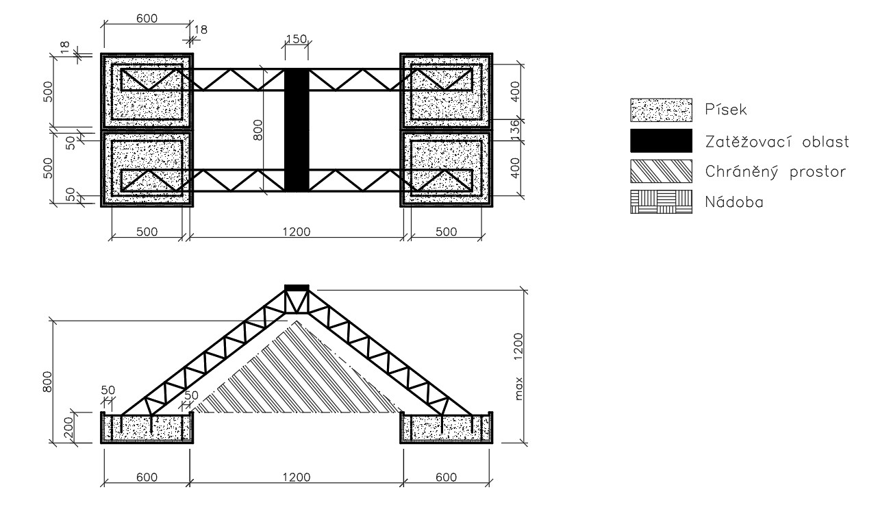
Figure 1 – Scheme of the structure – is correct. The stop is 30 mm high and 100 mm wide.
The width of the load table with the stop is 70 cm. Its full width can be used.
The term glued wood in the rules refers to the use of materials whose strength is significantly affected by glue, so the rules restrict the use of composite materials based on wood and glue. A glued profile consisting of thin wooden profiles less than 2 mm thick will be considered a composite material. The use of composites comprising sawdust, wood chips or small scraps bonded with glue, both purchased and home-made, is not allowed either. The model may be made up of longitudinally glued wooden profiles with a permitted minimum thickness of 2 mm, but the glue must not cover a significant part of the model surface. Provided that the glue does not cover a significant part of the structure, profiles meeting material requirements may be glued together. Profiles of min. 2×2 mm and max. 10×10 mm can be joined in this way.
The minimum dimension of the roofing model (including space for placing weights) is not specified in the longitudinal direction of the roofing. To meet the geometric requirements for load test No. 1, 8 weights with dimensions of 150 x 40 x 5 mm must cover a load area of 333 mm in one direction and of unlimited size in the other direction. The requirements for placing the weights are specified in the rules.
The use of wooden toothpicks is permitted provided the material requirements are met. They are made from permitted wood species and their cross-section is not less than 2×2 mm.
The Organiser provides the weights necessary for the load test of the model. The weights are placed directly on the structure built by the competitors. The structure is placed onto the load site as shown in Fig. 1 of the rules. The load site is provided by the Organiser.
The weights are placed directly on the structure during loading. If a support, distribution place, etc. is needed to place the weights, it must be a part of the model and is included in its mass.
The sand can only be used for placing or loading models inside the box. Outside the box, sand cannot be used – not even as a passive weight.
A drill used as a conventional handheld tool can be used freely while building the model. The use of tools using numerical control where the shape of the cut can be controlled by coded programmed instructions (CNC machines) is not allowed.
Due to the large number of models registered for the competition, the Organiser is not able to perform a preliminary inspection of the model’s compliance with the competition rules. The model´s compliance with the competition conditions will be decided upon by the jury at the competition venue. If you have a question about a particular structural solution, the competition Organiser will comment on it, but the solution will be published.
Testing the handling of weights in advance is not possible due to the equality of conditions in the competition.
Yes, the sand can be removed and placed into a container with a maximum volume of 20 l provided by the Organiser during the model placement on the test site and throughout the whole loading period.
The competitor can use any aids, tools to seat the model. The aids or tools must not become part of the model during its loading.
Sand can be used as passive ballast, but only INSIDE THE BOX below the maximum allowable sand height.
The structure is loaded successively with individual weights so that it is at rest before the next weight is placed. The judge at the table decides on the respective state.
Yes, if a weight falls off the structure, the load test can continue. Nevertheless, it is not permitted to deliberately remove weights from the structure. The assessment of the fall of a weight is at the judge´s discretion.
The structure must not be manipulated or supported in any way during the load test. The weights must be placed on the structure according to the rules (see Chapter Model test).
The basic and smallest profile is a 2×2 mm prism, any circular profile must encircle the minimum profile.
It is not possible to deliberately manipulate the weight after it has been placed on the structure. The moment the weight is placed on the structure, it becomes part of the structure. The structure must not be manipulated during the load test.
If the structure touches the stop at any time during the load test, a penalty will be added to the test result.
MATERIAL AND TOOLS
During the positioning of the model onto the test site, the contestants can use any tools of their own (rake, level, rule). The tools must not become part of the structure during its loading.
Plywood can also be used as a planar element. The materials can be machined with conventional hand tools, no laser or water jet, CNC machining, etc. are allowed.
A drill is considered as a common hand tool and, therefore, it can be used.
Creating your own profiles from permitted materials is allowed.
Conventional hand tools also include power-driven tools such as a hand drill, a circular saw, a jig saw and a hand milling machine. These tools can therefore be used. The use of numerically controlled tools where the shape of the cut can be controlled by coded programmed instructions (CNC machines) is not allowed. Compliance with this restriction must be proved by an affidavit.
Note: The aim of this restriction is to maintain a roughly level playing field for the competitors regardless of their technological background and financial capabilities.
Threads and strings of cotton and other natural materials are allowed.
Yes, the use of string made of natural materials is allowed.
No, paper does not meet the material requirements.
No, paper does not meet the material requirements.
STRUCTURE
The loading area must be horizontal to allow the placement of the weights. The shape of the structure is not limited, but it must allow the connection of the loading area. Note: The loading area represents a conveyer with a respective own weight.
The height of “max 1200 mm“ refers to the position of the weights. The weights can be placed lower but neither the structure, nor the weights can intrude into the protected area 800 mm in height. The shape of the structure is not limited. This means that the structure may even be situated above the loading area. Note: The loading area “represents” a conveyer in the model.
The conveyer width is specified as 150 mm. It corresponds to the dimension of the weights, therefore, it cannot be smaller.
The model must contain a space with an area of 150×800 mm, where the weights will be placed. It does not have to be marked.
The supporting method is not specified in any way. The structure must support the conveyer belt, the shape of the supporting structure is limited by the protected space and the maximum dimensions.
Weights can only by placed on the loading area. The area must have dimensions of 800×150 mm and be horizontal.
The spatial arrangement of the structure that carries the loading area is arbitrary, provided the geometric requirements are met. For example, compliance with the dimensions and horizontality of the loading area.
The loading area does not have to be a planar element. The geometric requirements must be met (e.g. compliance with the dimensions and horizontality of the loading area).
It is necessary to comply with the specified geometric requirements. The form of the design solution within the constraints is up to the contestants. Whether the loading area consists of the load-bearing structure itself or an additional auxiliary structure is identical in terms of the rules.
Planar elements such as shear stops are allowed.
No, strings do not meet the requirement for the loading area planeness.
MISCELLANEA
Students from the Faculty of Mechanical Engineering CTU in Prague can participate in this year’s Hall of the Year Academic as they meet the condition of a “university with technical orientation”.
The order of teams is determined by the organisers on the competition day. The parameters of setting the order are not public.
The rope must be on the model from the moment of acceptance, including any potential release mechanism. The rope can be released during loading. The model must not be modified in any way from the moment of acceptance to the start of loading.
Yes, a competing team can protest. Protests against compliance with material conditions and the course of the load test can be lodged within 15 minutes after the end of the load test of the respective model.
Photos from the event will be displayed on the competition website.
The load simulates material on a conveyor belt. It is, therefore, not possible, e.g., to load it only above the supports. The load must be distributed evenly even in the second phase.